So You Want to Build a Telescope? Think: Junk!
 I
did. It was a common enough thing when I was a kid in the 60s, and
I did it a lot when I was quite young. I had Scotch-taped together
a sort of pirate spyglass out of paper towel tubes and a couple
of old lenses I had gotten from Uncle Louie when I was only 10.
It wasn't much of a telescope, but it hadn't taken any money or
much time, either, and its view of the Moon was breathtaking. I
did. It was a common enough thing when I was a kid in the 60s, and
I did it a lot when I was quite young. I had Scotch-taped together
a sort of pirate spyglass out of paper towel tubes and a couple
of old lenses I had gotten from Uncle Louie when I was only 10.
It wasn't much of a telescope, but it hadn't taken any money or
much time, either, and its view of the Moon was breathtaking.
My parents bought me
all the necessary optics for an 8" Newtonian telescope for
my 8th grade graduation in 1966, and I set about furiously building
a tube and mount for it. This took me until the fall of 1966, but
the telescope, when it was completed, astonished me at what it would
reveal of the night sky.
That was over 40 years
ago, and I mostly blundered my way along, guided by library books
like Jean Texereau's How to Make a Telescope. Not long after,
I discovered the several short books (almost pamphlets) by Sam Brown
on telescope making, and I still consider them the best guide for
building simple Newtonian scopes ever published. The pamphlets were
later gathered into a single bound volume called All
About Telescopes,
which is still available from Edmund Scientifics ($14.95—cheap!)
and is a must-have for anyone even contemplating a home-constructed
telescope, and especially one made mostly from junk. Sam Brown liked
junk—he was writing in the early-mid 1960s, when money was
scarcer than it seems to be today—and he made excellent use
of it. The book is mostly illustrations, and those mostly superb,
all hand-drawn by the author.
This Web page is not
a tutorial on building telescopes; Sam Brown can give you that.
This page is a picture book of some of the telescopes I've made
since 1966, to give you an idea of what's possible, as well as convince
you that a geeky 8th grader working with nothing but hand tools,
scrap lumber, and pipe fittings, can unlock a gateway to a side
of the universe invisible to human eyes. Some of the photos are
ancient and badly taken, but bear with me: I have newer and better
photos of some of those same old items.
The telescopes here will
not perform like a Meade or a Celestron, and building a computer-controlled
drive is something I never managed. On the other hand, you won't
have to spend $4000 and up to look at Jupiter or globular clusters
like M13. Obession
Telescopes are fine if you're obsessed, but if you're a Maker
and are looking for an interesting new species of project, well,
consider it. The optics can be purchased ready-made; grinding your
own mirrors is mostly a lost art these days. The rest of it, as
you'll see, is hand-tool territory. I make telescope parts with
a lathe because I have a lathe, but I made telescopes parts
in my dad's vise long before I had anything better than a hand drill.
Parts and optics for
home-built telescopes are still available. Here are some places
to look:
Meridian
Telescopes Scope
City Scopetronix
Surplus
Shed
Also, you see telescope
parts and optics come up on eBay fairly regularly.
|
|
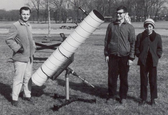
The Texereau Square-Tube 8" F8
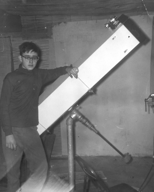
This photo is from September
1966, just after I had started high school and just before I had
completed my original square plywood tube 8" scope. (And yes,
that's me at 14. Egad.) The tube was 1/4" plywood with 1X1
pine stringers in the inside corners and 1/2" plywood strengtheners
on each end. There was a hinged hatch (not shown in this photo)
for installing and removing the main mirror. The tube design was
verbatim from Texereau; I did not have the Sam Brown material at
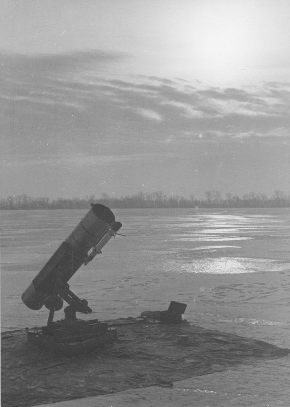
that point. Below is a better photo of the scope at my family's
summer place near Third Lake, Illinois, about a year later:
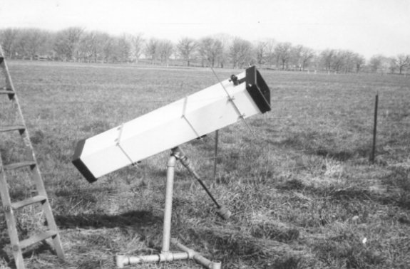
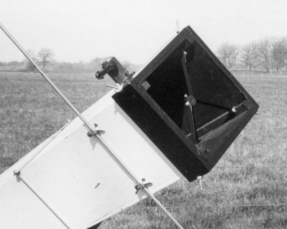
The diagonal mirror was
supported by a spider mount made entirely with hand tools. The rod
on the side supported a camera mount using chem lab ring stand fittings.
(The camera mount itself is not shown here, and I don't have a photo
anymore.)
Below is a drawing of
how a Newtonian telescope works. (Drawing from WikiCommons.) A parabolic
mirror (left) reflects incoming starlight to a focus. However, the
light cone is reflected 90° by the diagonal mirror so that the
focus point occurs at or shortly before the eyepiece. A rack-and-pinion
mechanism allows the eyepiece to be moved along the light cone's
axis, so that the lenses pick up the light at just the right point
to focus the image at your eye.
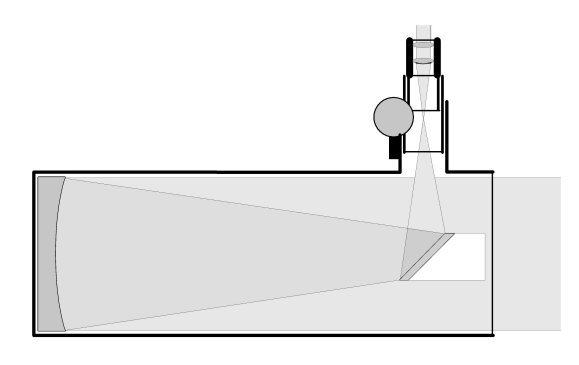
People often wonder if
the diagonal mirror casts a round shadow at the center of the image,
but it doesn't. The diagonal mirror cuts down a little bit on the
amount of light that reaches the mirror, but because it only blocks
parallel rays, its shadow is dispersed throughout the light cone
and is not seen as a blockage.
|
|
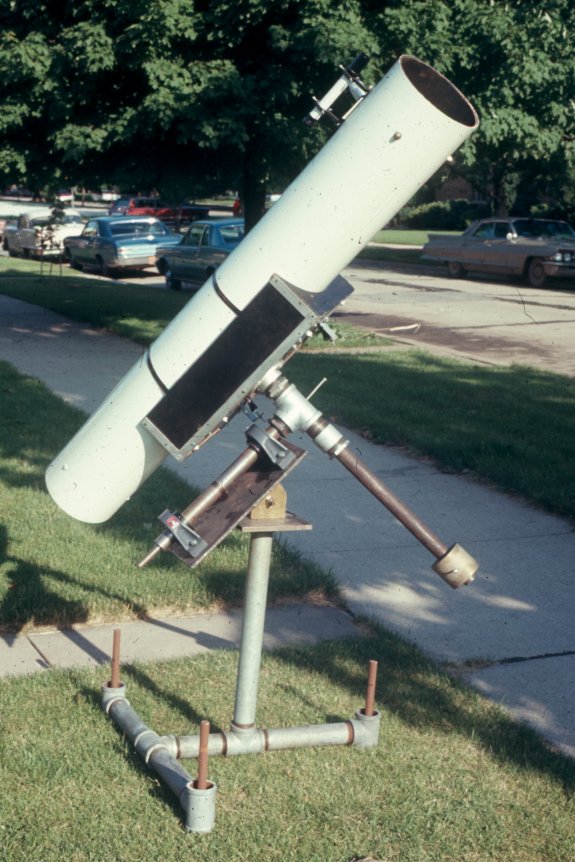
The Spiral-Tube 8" F8
I used the
plywood tube as shown above for two years. The tube was heavy and
ungainly, and I swapped in a length of 10" spiral aluminum
vent pipe (the type you see up in the ceiling of techno coffeeshops)
in 1968, making for a much, much lighter telescope:
The pipe
mount is the same, and I simply built a new tube saddle that would
accept a round tube. (I did learn in trying to paint the pipe mount
black that galvanized iron pipes do not take paint very well. Paint
will flake off in a matter of days. Leave 'em as they come.)
Note that
this telescope still exists. Not only that, it's the scope I probably
use more than my larger, more elaborate 10" scope that I'll
discuss a little later. The reason? It's light, and simple, and
easy to schlep around. Below is a photo from 2003, and shows the
scope essentially as I use it today:
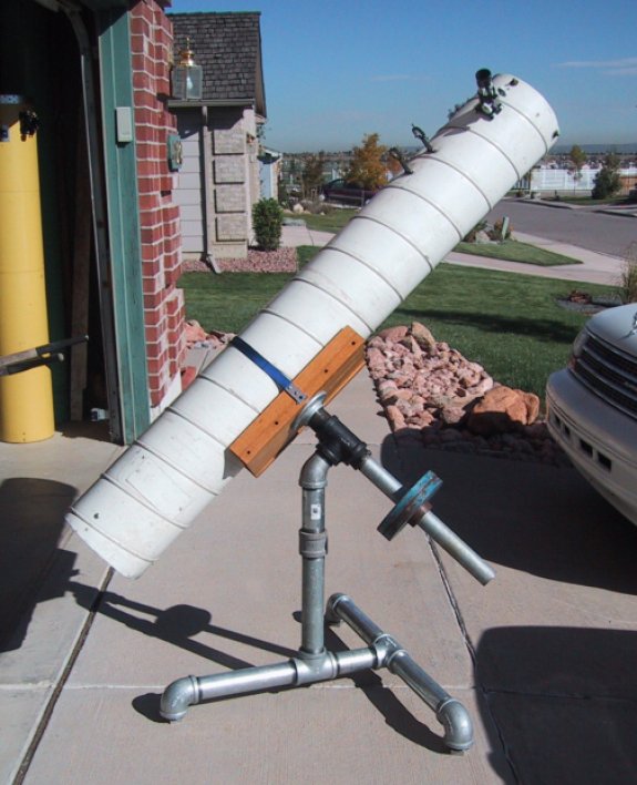
All of the
pipe fittings except for the counterweights axis are standard, Home
Depot 2" pipe size. (2" pipes are actually larger than
2" in outside diameter; the 2" is roughly the inside diameter.)
The main pipe tee is a black iron fitting that I found and painted
in 1966, and is the only original part of the mount that remains.
The counterweight shaft is 1 1/2" pipe for a simple reason:
It's a little less than 2" outside diameter, and standard bench-press
weights have a 2" center hole and will fit on it. A 2"
shaft collar I scrounged somewhere holds the weights to the pipe,
but a very short section of 2" pipe drilled and tapped for
a 1/4-20 machine screw will also serve.
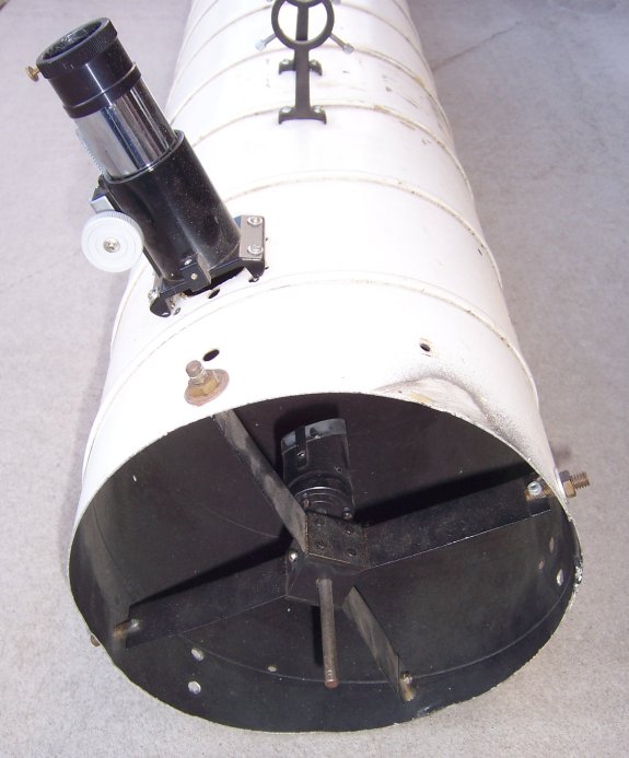
There's
not much in a Newtonian telescope, really. The main mirror sends
light up to a smaller mirror at the opposite end of the tube, which
reflects the light cone at a right angle through the wall of the
tube and into the eyepiece holder. This smaller mirror is called
the diagonal, and is held in place in a block suspended from
four thin vanes of metal under tension. It seems nonintuitive, but
having the central diagonal mirror does not cast a black
spot in the center of your visual field!
The "spider
mount" shown below is hand-made but took some lathe work. However,
I made a similar one in 1966 using nothing but a hand drill, and
it worked beautifully.
The tube
saddle is Home Depot oak wood with a single length of nylon strap
looped around the tube to hold it in place. There isn't even a radius
cut in the wood; I simply calculated three points of contact for
the 10" diameter vent pipe and arranged the side pieces so
that the saddle as a whole "grips" the tube at those three
places.
The main
pyrex glass mirror is held in place and adjusted in a mirror
cell, which sounds grander than what it is: A spring-tensioned
tilt-table made of scrap plywood, hardware store shelf brackets,
and three springs that (in my case at least) came out of the focus
yoke of a biggish 1950s TV set. (Ace Hardware still carries serviceable
springs in their wonderful little plastic drawers of odd parts.)
Three rubber bumpers glued to the plywood disk support the mirror,
which is kept from moving sideways by three flat brackets bent slightly
in a vise at one end, and padded with cloth bandage tape.
Three 1/4-20
flat-head bolts are attached to the plywood disk 120° apart
and about 1 1/2" in from the edge. The bolts pass through the
springs and the holes drilled in the aluminum sheet base plate.
1/4-20 wing nuts hold the cell to the base plate, and allow the
tilt of the mirror to be adjusted fairly precisely.
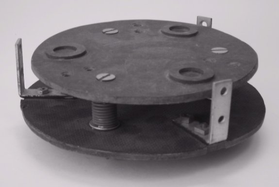
Below is
a photo of a mirror cell for a 6" mirror, which I made for
a friend using scrap Masonite. You can get a better view of the
springs and tilt bolts without the mirror. The three brackets that
hold the mirror in place horizontally are not shown, but you can
see the three sets of holes where they were later attached. The
mirror rests on three rubber garden hose washers glued to the masonite
disk:
A decent
8" F8 parabolic primary mirror will cost you from $200 - $300
depending on what it's made of and how accurate the curve is. The
whole telescope should come in under $500 if you shop well and use
scrap lumber and metal where possible.
The Lane Tech High School 8" F8
Once I got into high
school, I immediately joined the Lane Tech Amateur Astronomical
Society, and discovered that whereas the club did have a completed
telescope, all that existed was the tube assembly and optics. They
had been given some odd bits toward a mount, but nobody there knew
enough to put it all together. So bang! I decided to build on my
experience and finish the club scope. Here it is, and by now some
parts should look familiar:
|
|
|
I hadn't
taken machine shop yet (that would come the following year) but
once I had the design sketched out, one of the other older members
of the club did the machine work. The three brown rods are actually
1" threaded steel from somebody's scrap pile, screwed into
three pipe plugs drilled and tapped with the same thread. They allowed
precisely leveling of the mount, though they were a couple of inches
too long. The 1 1/2" cold rolled steel polar shaft was turned
down to 1/2" at the end to accept a worm gear and thus be motor-driven
to follow the rotation of the Earth. (Alas, as best I know no one
ever finished the motor drive.)
Whewn the
photo was taken the mount was complete but needed some tweaks: There
was no brake on the polar shaft, and the vertical pillar was about
eight inches too high. Both problems were eventually solved. I don't
know whatever became of the scope, but I hope it's still at the
school somewhere, even forty years on.
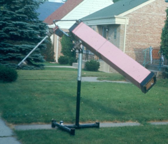
The Turn-on-Threads 8" F8 Porter Springfield
This one is a little
bizarre. In 1968, after I had replaced the square plywood tube with
the spiral aluminum one, I had this square plywood tube in the corner
of the basement. During one fevered summer week between sophomore
and junior years of high school, I attempted to turn it into a Porter-Springfield
mount. This is a brilliant if problematic way to mount a telescope
such that the eyepiece never moves, regardless of where the telescope
is pointing. It's a tough thing to explain. First, look at the scope
as a whole:
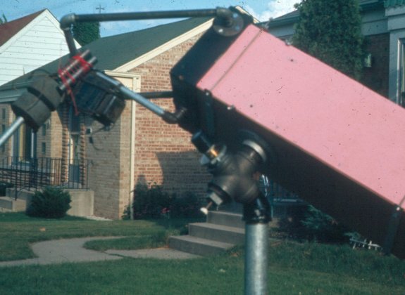
Now, take a look at a
closeup of the eyepiece section at the center:
|
|
|
(These are
the only two photos that have survived.) The heart of the mount
is a 2" iron pipe cross, which turns on the threads of the
45° street elbow (here, painted black) atop the galvanized pipe
vertical pillar. Inside the center of the pipe cross is a small
diagonal mirror, which turns the light cone up to an eyepiece mount
(look for a glint of brass.) The telescope thus has two secondary
mirrors: one in the conventional Newtonian position at the center
of the tube assembly, and a second inside the pipe cross. No matter
which way the tube points, the light cone is reflected first into
the center of the pipe cross, and then up to the eyepiece. (See
if you can rotate the two scope axes in your head to envision what
I mean!) In use, the observer looks comfortably down into the eyepiece
(here a black cylinder above the brass sleeve) and never has to
crane his neck.
This mechanism
was invented by the legendary Russell W. Porter in 1920 or so, and
while brilliant, it has drawbacks: Balancing the tube is diabolical,
and yes, that is an old TV power transformer tied to the balance
assembly. It worked, but the pillar was too tall and too wobbly
(such things should be built from stouter pipe and set into cement
bases) to work well. It was, however, the best that I could
do at 15 with little money and in truth not a lot of skill. It may
be the only turn-on-threads Springfield pipe mount ever attempted,
and (I guess) I'm proud of that, even though I never used it very
much, and abandoned the square tube entirely soon afterward. I was
in the thick of another project by that time, and by junior year
was pouring everything I had in time and money into it: A 10"
F6.7 Newtonian scope, for which I ground and figured the primary
mirror all by myself.
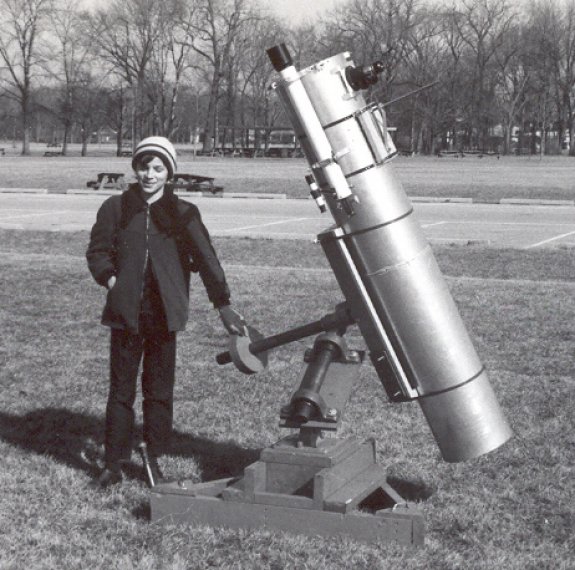
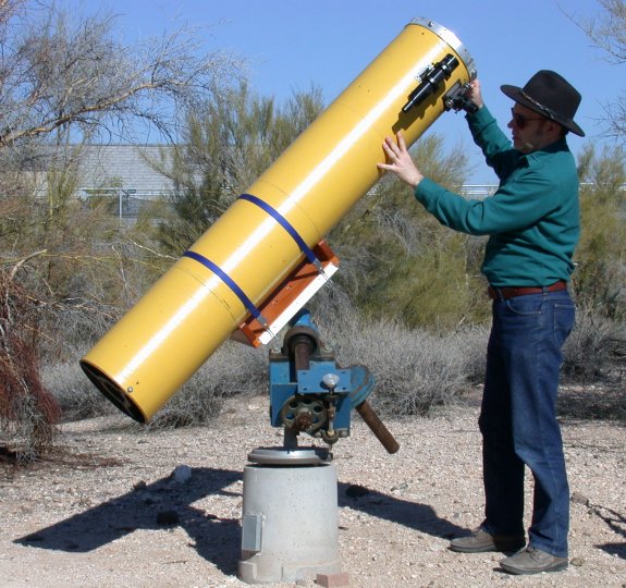
The 10" Newtonian F6.7
And oh my lord, what
a project it was. I had begun it during my sophomore year at Lane
Tech, by purchasing a 10" Edmund Scientific mirror grinding
kit from a friend of mine, who had bought it for $40 and, after
discovering that he did not have the time or equipment to finish
it, sold me the works for $10. (Remember, this was 1968, when $10
was actually big enough to matter.) I started grinding it in the
basement, atop an old and defunct wringer washing machine. However,
the further along I got, the more I felt I would need help, and
in the summer of 1968 I enrolled in a mirror-making class at Adler
Planetarium on the Chicago lakefront. That was an act of consummate
wisdom, as polishing and figuring mirrors is not something easily
done in the basement without certain gear that I was too poor to
buy and too dumb to make. And so I spent the entire summer of 1968
running down to Adler all by myself on the subway, endlessly stepping
around a water-filled 55-gallon drum, scraping one glass disk over
another with a water slurry of carborundum in between, and taking
abundant advantage of the on-staff expert assistance.
It was a huge project
for one so young (I didn't even have a driver's license at that
time) but I saw it through, and by late August it was finished:
A 10" F6.7 mirror figured to an astonishing 1/20 wavelength
accuracy, aluminized and ready to use. Alas, I did not have a telescope
to put it in, as all my time had gone into creating the mirror.
So it was almost another whole year before I managed to score a
tube, bearings, shafts, and other parts and get them all pulled
together into workable form. The scope saw first light right before
Christmas 1969, and the photo below is from January 1970:
Here's a closer view,
on that same day, this time with me at the eyepiece:
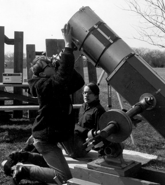
The mount was not entirely
finished at this point. I had not created a friction brake for it,
so the friction came from jamming pieces of scrap plywood and masonite
between the equatorial head plate and the 2" steel polar shaft.
Remarkably, that haywire system worked well, but if the scope were
spun too quickly in right ascension, the rapid movement of the polar
shaft would kick the plywood out of its place, and the now-freewheeling
scope would keel over and whack me in the head. (This happened more
than once.)
The triangular wood base
was peculiarly effective, and interesting because when I designed
it, I was assuming that it would be used as a cement form allowing
me to pour a concrete base. (I hadn't calculated the weight of such
a thing, and so did not realize that I would not have been able
to move it once it was cast.) However, the triangle (made of scrap
2 X 8s) was so heavy and sturdy all by itself that I said what the
hell, and just used it as a base and not a form. The wood triangle
base stayed with me until 2000 or so, when I realized that a north
Scottsdale colony of termites had hollowed it out and ruined it.
In the spring of 1970
I added a polar worm gear and motor drive to the equatorial head.
However, I did the figgerin' wrong, and the drive turned the
scope the wrong way. That is, the motor drove the polar axis
from west to east instead of east to west. It was acutely embarrassing,
and surprisingly hard to fix, because I had designed the mounting
plates for that particular motor, and then had them welded to the
equatorial head. I looked for a motor that would fit "the other
way" and never found one. To this day, that scope has never
had a motor drove that worked correctly.
|
|
|
Optically,
the scope was (and is) awesome. Mechanically, it has always been
a nightmare. I appreciated the importance of rigidity and mass in
telescope mounts, but I was also constrained by what materials I
could scrounge at school. The equatorial head was made of 1/2"
scrap steel plate, and 2" solid cold-rolled steel shafts turning
in brand-new ($20 each!) Fafnir pillow-block ball bearing assemblies.
The head assembly alone weighed 120 pounds without the declination
shaft, and was pure murder to haul around.
Development
on the scope slowed down radically after I graduated high school,
because I no longer had access to machine tools for working steel
and brass. I got a lathe again in 1978, but by then I was a little
burned out on the big scope, and didn't add much to it as the years
went on. I worked on the tube and optically assembly here and there,
and converted the tube from aluminum to wax-impregnated Sonotube
concrete form in the mid-1970s. I covered the Sonotube with yellow
ConTact paper because no paint would adhere to the wax coating.
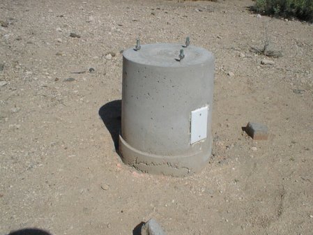 I
still have the 10" scope, and in 1999 I began work on a poured
concrete pillar to replace the termite-eaten wooden triangle base.
What I did is dig a biggish hole in the desert caliche (a chalky
stone that underlies a thin layer of dry soil in the Sonoran desert)
and used an inverted plastic bucket that had once held swimming
pool chlorine tablets as a cement form. Pete Albrecht helped me
pour it, and we embedded an electrical junction box and three stainless
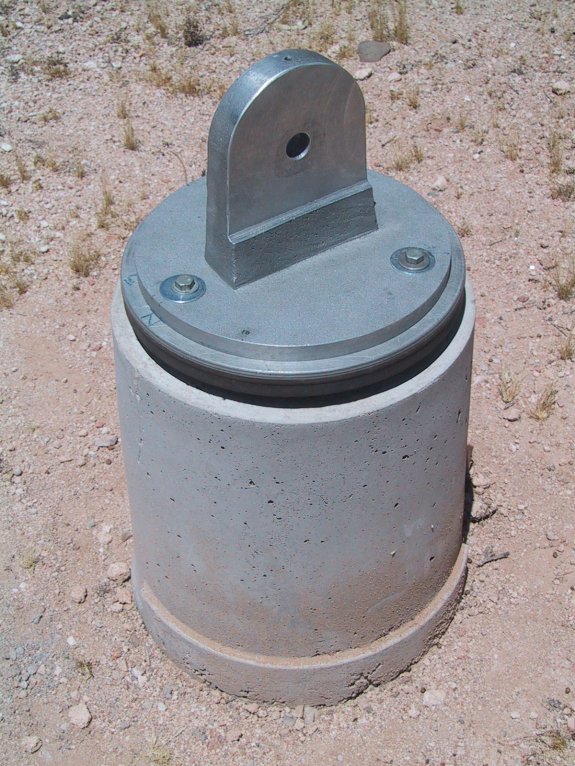
steel bolts in the concrete. Later the bolts allowed us to attach
the new equatorial tang, which was an aluminum casting poured in
a local foundry and machined on my lathe. I
still have the 10" scope, and in 1999 I began work on a poured
concrete pillar to replace the termite-eaten wooden triangle base.
What I did is dig a biggish hole in the desert caliche (a chalky
stone that underlies a thin layer of dry soil in the Sonoran desert)
and used an inverted plastic bucket that had once held swimming
pool chlorine tablets as a cement form. Pete Albrecht helped me
pour it, and we embedded an electrical junction box and three stainless
steel bolts in the concrete. Later the bolts allowed us to attach
the new equatorial tang, which was an aluminum casting poured in
a local foundry and machined on my lathe.
It was beautiful.
(It helped some—nay, critically—that Pete is a mechanical
engineer.)
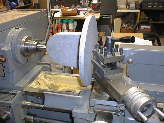
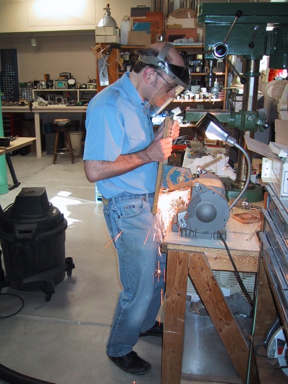
Working
with all this massive metal was a trial at times. By 2002, I was
50, and not the muscular stud (ha!) I had been in college. Below
is a photo of me trimming up the 60-pound equatorial head base plate
that I had created in high school, so that it would fit the new
aluminum pier and tang. Man, that was a job. My back hurt for weeks.
Carol says, however, that I was wearing the face mask in the wrong
place...
I got some
good use out of the scope in the years 2000-2002, until my publishing
company imploded and we left Arizona for Colorado Springs. It was
much easier to deal with a permanent pier installation, and after
I removed the tube and saddle from the mount, I threw a cheap plastic
trash can over the equatorial mount and pillar to keep what little
rain we received off of it.
It's hard
to see the details in the polar gear, so below is an enlarged copy
of that portion of the equatorial head. There's a bronze 96-tooth
gear on the end of the polar shaft, with a three-point friction
brake holding it in place. This allows you to move the telescope
without stripping the gear teeth: 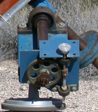 A small bronze plate "squeezes" the big worm wheel against
the machined end of the steel polar shaft. The worm wheel thus is
not pinned or set-screwed to the polar shaft. Move the telescope,
and the brake slips, but move the worm wheel slowly, and it will
drive the telescope in right ascension.
A small bronze plate "squeezes" the big worm wheel against
the machined end of the steel polar shaft. The worm wheel thus is
not pinned or set-screwed to the polar shaft. Move the telescope,
and the brake slips, but move the worm wheel slowly, and it will
drive the telescope in right ascension.
An aluminum
handwheel allows you to move the polar axis in finer increments
than simply shoving on the tube. The four empty bolt holes used
to hold a second pair of pillow blocks and a second stage of worm
gear reduction, with a synchronous motor hanging off the right end
of the shaft.
I had cornered
an odd but powerful geared-down stepper motor in the summer of 2002,
with the intent to couple its driven hub to the small shaft, right
where the handwheel is in the photo. Alas, life got lively about
that time, and the stepper motor is still in a box.
I will admit
with some regret that I have not had the 10" scope assembled
and working since we moved to Colorado in early 2003. I don't have
a place to put a concrete pier, and the energy and time to re-create
the late wooden triangle base have escaped me. It's just easier
to use that junky old turn-on-threads 8" scope that saw first
light in 1966.
|
|
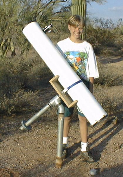
Brian's 6" Newtonian
 When
my older nephew Brian got to be 13 (1996) he expressed some interest
in building a telescope. (We do not have children of our own.) He
and his brother would come out to Arizona every other year, and
we would always tackle a build-it project together. The telescope
was very simple, and it drew on the design of the original 8"
I had begun in 8th grade thirty years earlier in 1966. When
my older nephew Brian got to be 13 (1996) he expressed some interest
in building a telescope. (We do not have children of our own.) He
and his brother would come out to Arizona every other year, and
we would always tackle a build-it project together. The telescope
was very simple, and it drew on the design of the original 8"
I had begun in 8th grade thirty years earlier in 1966.
It was a 6" Newtonian,
which made it much smaller and lighter (and easier to wrestle with)
than even the 8", and for starters it's not a bad size. I ordered
the tube and all the optical path parts from ads in the back of
Sky & Telescope Magazine, and Brian and I put it together
over a week of hot afternoons in the summer of 1996. The photo here
shows the scope mounted on the 2" pipe pillar I had sunk into
concrete back in 1990 and otherwise used for my 8" scope. A
2" pipe pillar is big enough for either a 6" or an 8"
Newtonian; it's not rigid enough to hold the weight of an ambitious
10".
The simple tube saddle
is made of particle board, one slab in the center with a pair of
slabs cut to fit the curve of the tube on each end. The blue band
is nylon strap from a camping store. All the rest of the base are
2" pipe fittings identical to the ones I used on my 8"
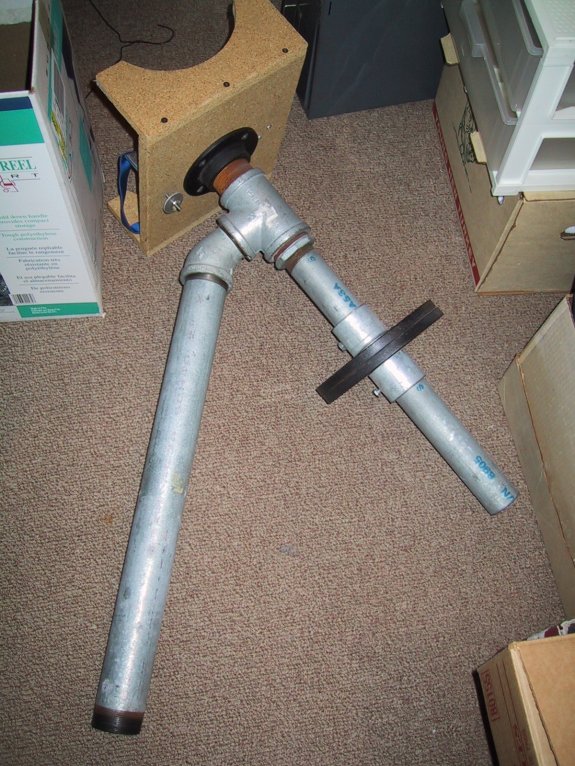
scope. The photo below is a little awkward, but it shows very clearly
how the mount goes together. The black fitting is a 2" black-iron
floor flange that I had in the junkbox, but galvanized flanges work
just as well, and are easier to find.
It's a great little scope,
and I am very proud that Brian still has it and still uses it, even
though he's now a banker in downtown Chicago helping cut deals that
run to nine figures with monster corporations. Kids love building
things. They grow up so fast. Don't let the chance go by.
|
|
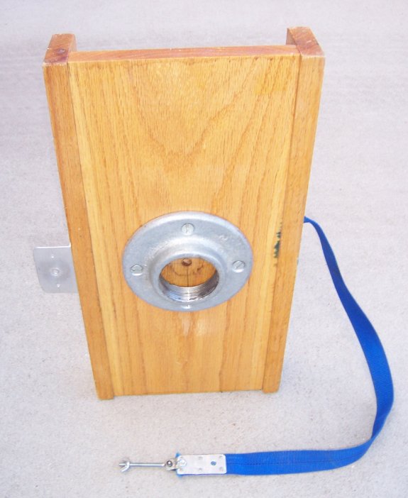
The Enlarger Lens Altazimuth
This was
an experiment, and another joint project , this time with my younger
nephew Matt. Carol's father had left us an old but intact enlarger
lens assembly when he died in 1990. I had it on the shelf, not sure
what to do with it, but itching to see if it could become the front
end of a telescope. In 1999 Matt and I decided to give it a go.
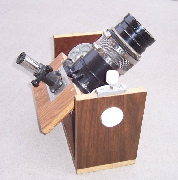
It's all
junkbox stuff and telescope leftovers; the focusing mount was the
very first one I had bought with my allowance at the American Science
Center in Chicago in 1966. The lens is attached to a black PVC toilet
mount flange with a plumbing squeeze clamp exactly for that purpose;
miraculously, the enlarger lens was just a little smaller than the
toilet flange. (Sometimes you get lucky. That would have been a
tough nut to crack otherwise.)
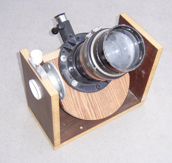
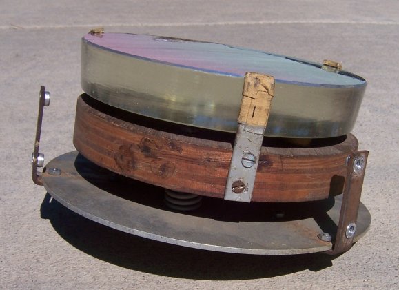
The photo
below is the telescope with the big lens tipped forward so that
the prism is visible. The right-angle prism was a surplus item (marked
"Eastman Kodak") that I had bought on spec at a hamfest.
The prism mount is crude but it worked. The rest is scrap particle
board plus a couple of pieces of scrap oak.
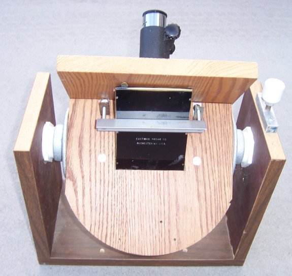
There was
originally a baseplate, also of scrap particle board, on which the
assembly shown above pivoted on an inexpensive Home Depot lazy susan
bearing. The baseplate and bearing plate got soaked with sewage
during a plumbing malfunction in 2006 and had to go.
How was
it as a telescope? So-so. The exit pupil is too big and there are
mondo color fringes on bright stars. The Moon looks great, though,
and it works tolerably well as a terrestial scope, if you can get
past the fact that the field is reversed right-for-left. I may have
done something wrong, but then again, enlarger lenses are not designed
to focus at infinity so I shouldn't expect perfection. It was a
quickie project to prove a hunch, and for that it worked just fine.
|
|
My Recommendations
A 6"
Newtonian is easy to build, quite light, and relatively inexpensive.
It's a good size for a kid project treated as a project and not
a passion. However, if astronomy is your passion, go for
an 8". Your light gathering power (which is what matters in
telescopes like this, not magnification!) is almost twice what it
is in a 6" scope (compare the surface area of a 6" mirror
to an 8" mirror) and yet neither size nor weight increase by
a factor of two. An 8" Newtonian can be mounted on easy-to-get
2" pipe fittings and pipe sections, which are the largest size
you can typically get without special ordering.
You might
well wonder if it's then not better just to scrape up the cash and
buy a Meade GPS or one of the Celestrons. You get computer control,
a more compact physical design, and (as my friend the well-known
astrophotographer Michael Covington once told me) you will spend
less time looking for things and more time looking at
them. (Finding faint celestial objects with a pipe-mount scope is
an art in itself.) And that's true: With a Meade you can basically
say, "Go find M31." If M31 is above the horizon the motors
will begin turning, and when they stop, M31 will be in the eyepiece.
On the other
hand, when you work through Sam Brown's All About Telescopes
and piece the instrument together all by yourself, you will know
how it works. Intimately. You will learn a great deal about
nuts, bolts, pipe fittings, and hand tools. And when it's done,
you will line up the Moon or Saturn in the eyepiece, steer your
friends or significant other in front of it, and listen to them
gasp with astonishment.
Junk? Sure.
Effective? Until you do it yourself, you have absolutely
no idea!
|
|
|
|
|
|
|
|
|
|